-40%
Tibbit #03_1: Two Low-Power Relays (Configuration 1), M1S
$ 3.69
- Description
- Size Guide
Description
Tibbit #03_1: Two Low-Power Relays (Configuration 1), M1STIBBIT_03_1
This is a Tibbit module — part of the Tibbo Project System that allows you to build your own custom embedded device with only the components you need. Start with a
Tibbo Project PCB
, add
Tibbits
like this one, then place the built design into a
Tibbo Project Box
to complete your product.
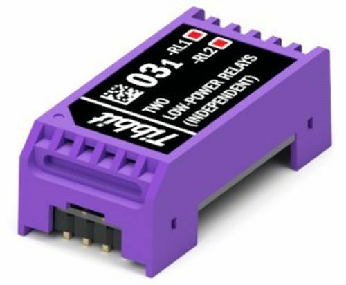
Tibbit #03_1: Two mechanical low-power relays with independent normally opened terminals.
These relays have contact capacity rated at 1A/30V (resistive load).
To activate a relay, set the corresponding control line LOW. When left unconnected, control lines default to HIGH (and, hence, relays are off).
Combine this Tibbit with a terminal block
C
Tibbit
#20
(nine terminal blocks) or
#21
(four terminal blocks).
There are two red LEDs each of which is connected to a relay control line. They light up for the LOW state (i.e. when the corresponding relay is activated).
Form:
M1S
Power:
5V; consumes 60mA
Mates with:
#19
,
#20
,
#21
Similar to:
#03_2
,
#06
,
#07
, #15
M1S Tibbit Modules Overview
M1S
Tibbits are single-width modules occupying one standard
M
socket on a Tibbo Project PCB (i.e.
TPP2
or
TPP3
). Their footprint is roughly
7 × 14
"squares" (one "square" is
2.54 × 2.54 mm).
The
M1S
modules are 12.5mm high.
M1
modules have two rows of 6 pins:
Pins 8-11
are control lines
A-D
. They provide the interface to programmable modules or other microcontrollers. On Tibbo Project PCBs, these pins are connected to the main processor.
Pins 2-5
are I/O lines facing the outside world. On Tibbo Project PCBs, they go to
C
Tibbits.
Pins 6 and 12
are the GROUND and +5V power pins. Most Tibbit Modules consume (take) 5V power. There are also power supply Tibbits that generate 5V power from a variety of sources. Those
output
5V through
pin 12.
Pins 1 and 7
are for the additional +15V and -15V voltages. These are optional and only needed by few Tibbits. A special power supply Tibbit (
#12
) generates ±15V from the main 5V power.
